Oct. 9, 1962 A. ISMACH MULTI-DOSE JET INJECTION
DEVICE Filed Deo. 14, 1959 5 Sheets-Sheet 1
ATTORNEYS.
Oct. 9, 1962 A. lsMAcH 3,057,349
MULTI-DOSE JET INJECTION DEVICE Filed Dec.
14, 1959 5 Sheets-Sheet 2 IN VEN TOR. AA RoN /sMAcH
BY //W. @7W QM a@ /9 TTORNEYS.
Oct. 9, 1962 A. lsMAcH 3,057,349
MULTI-DOSE JET INJECTION DEVICE Filed Dec.
14, 1959 3 Shee'cs-Sheet 3 IN V EN TOR.
74 AARON /sMAcH BY V @a ff/)dw ATTURNEYS.
United States Patent O 3,057,349 MULTI-DOSE
JET INJECTION DEVICE Aaron Isrnach, 3025 W. 32nd
St., Brooklyn 24, N.Y. Filed Dec. 14, 1959, Ser.
No. 859,510 12 Claims. (Cl. 12S-173) The present
invention relates to medical inoculant injection
instruments and more particularly to high speed
multidose hypodermic jet injection instruments.
The present invention provides a novel
combination of means for effecting a sterile
inoculation of vaccine or other medicament by
providing a fine jet of inoculating uid which is
impelled at high speed and with great pressure
under the skin of the subject to whom the
inoculant is administered. The invention makes
possible the delivery of an exactly metered dose
of a desired vaccine beneath the skin of a
patient without the use of a needle and in a
relatively painless manner without breaking the
surface of the skin.
The instant invention provides improvements
over prior methods of effecting inoculation by
means of a thin high pressure stream or jet of
vaccinating fluid, wherein multiple doses of
vaccine -are given -to a number of patients
without the need for reloading the injection
instrument with a new reservoir of vaccine
before each shot is administered. The present
invention is particularly novel and useful in
providing a jet injection instrument capable of
administering inoculation shots to a very large
number of patients within la very small interval
of time, without any necessity for sterilization
of the instrument between shots, without risk of
injury or crossinfection to the patient, and
with great accuracy in metering the required
dosage of inoculating fluid. In use, rates as
high as 4,000 patients per hour have been
achieved in administering a 1/2 cc. dose of
Vaccine.
It is an object of the instant invention to
provide a jet hypodermic injection device by
which inoculations can be given to more patients
in a shorter time, with much greater safety and
much more economically than was formerly
possible either with the conventional hypodermic
needles and syringes or with other types of
hypodermic injection devices.
It is another object of the instant invention
to provide a hypodermic jet injection device
which possesses an extremely high shooting rate,
which permits the vaccine being administered to
be changed from one type to another very easily,
rapidly, and under sterile conditions, and which
permits prescribed dosages of vaccine to be
altered very rapidly and accurately.
Another object of the present invention is to
provide a hypodermic jet injection gun which is
well balanced with a centrally disposed load,
which can be operated and comfortably held by
the operator in one hand, leaving the operators
other hand free to swab or grasp the patient,
which is relatively noiseless and free from
recoil, and which lends itself to long periods
of fatiguefree operation. The latter
characteristic of this invention is extremely
important when inoculations are being
administered by a high speed jet injection,
since if the gun is permitted to slip on the arm
of a patient when it is fired, a nasty cut may
result.
Another object of the present invention is to
provide a hypodermic jet injection device which
can be quickly and easily disassembled, which
can be easily and eiliciently sterilized by
autoclaving or other means, and which can be
readily serviced by using conventional hand
tools without the need for specially adapted
tools or devices.
Another object of the present invention is to
provide a hydraulic jet injection gun so
constructed that a failure in any one portion of
the gun will be isolated to that portion and so
constructed that there is a path to the
3,057,349 Patented Oct. 9, 1962 ICC exterior of
the gun near each seal in the mechanism. The
latter feature insures that if any one of the
seals should fail, iiuid (either inoculating
fluid or hydraulic fluid) will appear at the
surface of the gun adjacent to the seal and
enable the operator to immediately discern which
of the several seals has failed or is leaking.
Another object of the present invention is to
provide a hypodermic jet injection device which
is ideal for use in isolated areas where it is
difcult to obtain spare or replacement parts,
since the device uses standard components, and
is relatively trouble-free, and is easy to keep
in operating condition.
With the device of the instant invention only
the inoculating fluid goes below the skin level
of the patient, and it is relatively easy to
insure sterile operating conditions; whereas
with conventional hpyodermic injection devices
part of the device itself penetrates beneath the
skin and necessitates the most stringent
requirements for sterility in the older devices.
The present invention provides a hypodermic
jet i11- jection device, which requires no
sterilization either between shots or even when
the type of vaccine is changed, which delivers
accurately measured doses of vaccine once it is
vpre-set, which is not dependent upon the
operator `to control accuracy of the dose as
conventional devices are, and which creates no
danger of cross-infection, since nothing but the
inoculating uid itself penetrates beneath the
skin of the patient. The latter characteristic
is especially helpful in preventing the spread
of infectious hepatitis, and the danger of
spreading hepatitis infection is an outstanding
disadvantage of the older method of
administering inoculations by the use of
syringes and hypodermic needles. It is possible
for a patient to be a carrier of hepatitis and
capable of seriously infecting another patient
with the disease, although the carrier himself
may show none of the symptoms associated with
hepatitis. One of the outstanding benets
conferred by the invention in helping to prevent
hepatitis or other cross-infection, is that if
operation of the jet injection device is
commenced with the device in a sterile
condition, the gun will maintain its own st
erility..
AIt is another object of the present
invention to provide a hypodermic jet injection
gun comprising tWo separate but interrelated
pump mechanisms: a vaccine pump and a hydraulic
pump. Both pumps are self-priming and
exceptionally smooth Working in operation.
It is a further object of the instant
invention to provide a hypodermic jet injection
gun which is of an inestimable value for use
under emergency or epidemic conditions when it
is essential that a great many shots be
administered in the shortest possible time with
a maximum amount of safety. The efliciency of
design and simplicity of operation of the
invention obviate the need for a skillful
operator. Almost any intelligent person can
satisfactorily operate the gun after a
rudimentary amount of training.
Unlike most earlier hypodermic jet injection
guns, the instant invention is free from danger
of sucking fluid back from a patient either
during or after the firing cycle is completed so
that the danger of cross-infection is almost
completely avoided; this is obviously an
important advantage at all times, but is
particularly apparent when the gun is used under
emergency conditions. The characteristic ofthe
gun which permits it to be preset to deliver an
exceptionally accurate dose of vaccine and
repeatedly deliver this same dose each time it
is red is of great value when the gun is used
under any circumstances, but is particularly
important when the gun is to be used under
emergency, disaster or epidemic conditions by a
relatively untrained operator.
Broadly described, the present invention
comprises a hypodermic jet injection device
including vaccine pump means capable of
meteringan exact amount of inoculating iiuid
into a vaccine pump chamber, outlet valve means
providing a small outlet oriiice for vaccine
from the vaccine pump means, a piston forming
part of the vaccine pump means, combined
hydraulic pump and spring means for driving the
vaccine pump piston very rapidly but smoothly
into the vaccine pump chamber to expelV a
metered amount of vaccine through the outlet
valve oriiice in a thin stream under tremendous
force andpressure, and valve means for storing
and selectively releasing the force of the
hydraulic pump and spring means to drive the
vaccine pump piston.
Additional objects and advantages of the
invention will be settorthin part in the
'description which `follows and in part will be
obvious from the description, or may |be learned
by practice ofthe invention, the objects and
advantages being realized `and -attained bymeans
of the instrumentalities and combinations
particularly pointed out in the appended claims.
The invention consists in the novel parts,
constructions, arrangements, combinations, and
improvements shown and described.
The accompanying drawings, which are
incorporated in and constitute a part of this
specification, illustrate one embodiment of the
invention and together with the description,
serve to explain the principles of the
invention.
Of the drawings:
FIG. l is a central vertical section of the
device;
FIG. 2 is a fragmentary enlarged section
ofthe nozzle portion of FIG. 1;
FIG. 3 is a fragmentary enlarged section of
the actuatingvalves and hydraulic piston
portions of the device;
Y FIG. 4y is a section taken on the line 4 4
of FIG. 1;
. FIG.- 5 isacross-section of the vaccine
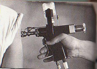
extracting tube; FIG. I6` is a side elevation of
the device in use and showingthesight port;
. FIG. 7 -is a plan section taken on theline
7-7 of FIG., 6;
FIG. 8 is a fragmentary section of the
comparable portion kor" FIG. l, but showing the
device cocked` and ready to eject vaccine.rk
It is to be understood that both the
foregoing general description and the following
detailed description are exemplary
andexplanatory, but Iare not restrictive of the
invention.
In accordance with the invention, a
hypodermic jet injection device is provided
having meansto meter a prescribed. dose of
vaccine, means to accumulate and apply force to
eject vaccine under pressure, and means to
control thefaccumulation and release of the
force. In the present preferred embodiment the
means to meter the dose of vaccinecomprises, a
vaccine pump having an intake valve and an
outlet valve, the means to Iaccumulate and apply
force comprises a hydraulic cylinder and spring,
`and the means-to control the accumulation and
release of force comprises a series of hydraulic
valves.
' Reference will now be made in detail -to
the present preferred embodiment of the
invention, an example of which is illustrated in
the accompanying drawings, and in which Ilthe
`means for accumulating and'applying force and
pressure on the metered amount of vaccine
comprises (FIG. 1) a hydraulic chamber 10, a
hydraulic piston 12, a spring` chamber 14, Ia
compression spring 16, and spring guide18.`
Thedevice includes a main body 19 which in turn
comprises a barrel 20` and grip 21 and the
hydraulic chamber and the spring chamber 14 are
formed in the barrel 20. The spring chamber
14-of the barrel 20 is closed with a square cap
22 to which a dosage adjusting screw24wis
threadedly engaged. At its interior end the
dosage adjusting screw 24 is provided with a
thrust ball l`bearing 26 which bears against one
end of the spring 16. The dosage adjusting screw
24'has an adjusting knob 28 secured to its
exterior end to per-mit hand operation of the
screw. At one end the spring 16 bears against
the thrust ball bearing 26 and at the other end
bears against the hydraulic piston' 12^so that -thei
spring-may be adjustably compressed between
these two bearing surfaces (thrust bearing 26
and hydraulic piston 12) by -turning the dosage
adjusting screw 24.
As embodied, the hydraulic piston 12 includes
a plunger 30 which reciprocates in a cylinder 31
formed in the forward end of the barrel 20. Also
Ias embodied, the means to meter vaccine
comprises a vaccine pump cylinder 33 formed by a
barrel extension 32 which is attached to the
barrel 20 by `a threaded'barrel extension cap
34. A vaccine pump piston 36 is secured to the
hydraulic piston plunger 39 at the forward end
of the plunger and the vaccine piston k36l
reciprocates in-the vaccine pump cylinder 33
responsive to movement of the hydraulic piston
12. Included in the vaccine pump piston 36 is a
sealing ring groove 38 in which appropriate
sealing rings may be mounted to seal the forward
portion, or lvaccine chamber 39, of the vaccine
pump cylinder 33 from the rear of the cylinder.
The forward portion of the barrel extension
32 is adapted to receive a closure member 40,
and the closure member` 40 is held rmly in place
at the end of the barrel extension 32 by a
nozzle cap 42 which is threadedly engaged to the
exterior lof the barrel extension 32. The
closure member 40 is provided with `a ball check
outlet valve 44 and carries appropriate sealing
rings. At its forward extremity the nozzle cap
42 carries a sapphire orifice insert 46 which is
bored to a veryclose tolerance and which
determines the diameter of the jet stream of
inoculating iluid.
A vaccine inlet valve 48 is carried by `a
member 50 which is secured to the top of the
barrel extension 32, and a vaccine inlet tube 52
leads from the vaccine inlet valve 48 to the
vaccine chamber 39 in the barrel extension 32. A
vaccine extracting 4tube 54 is wedged on the
tapered nose of the vaccine inlet valve 48 and
secured thereto by conventional means. The tube
54 includes a right angle bend so that .its rear
portion extends in a vertical direction when the
device or gun is in firing position.
Within the upright portion of the vaccine
extracting tube S4 is .an air vent tube 55 of
smaller diameter but concentric with the vaccine
extracting tube S4. The vaccine eX- tracting
tube 54 includes -a longitudinal port 56 by
means of which vaccine is withdrawn from a
conventional vaccine bottle 58 and into the tube
54.
The air vent tube 55 is provided with an air
lter 60 which in use would be filled with
sterile cotton to trap any impurities which
might otherwise lbe drawn into the vaccine
bottle 58 along with outside air as vaccine is
Withdrawn from the bottle.
A clip 62 (FIGS. 4 and 7) is secured to the
barrel 20. On top and centrally disposed on the
clip 62 is a U-shaped tube support 64 which is
Welded or otherwise secured to the clip 62. The
Vaccine extracting tube 54 is held by the
U-shaped tube support 64 and the support 64 is
provided with two small stops 66 which come to
rest against the upright portion of the tube 54
and determine the position of the clip 62 on the
barrel of the gun stock 20. The U- shaped tube
support 64 also acts as a positive stop for the
vaccine bottle 58 when the bottle is pushed onto
the up- `right portion of the tube 54 to provide
the vaccine supply for operation ofthe gun.
The U-shaped tube support 64 secures the
vaccine extractingtube 54 lagainst horizontal
movement and a spring loaded retractable vaccine
extracting lock 68 secures the needle tube 54
against vertical movement. The lock 68 yand the
tube support 64 thus cooperate to hold the tube
S4 in 4a rigid, upright, and easily accessible
position and at the same time prevent the
relatively delicate vaccine extracting tube 54
from being easily dislodged and Abent or
otherwise damaged. The tube support 64 also acts
as a channel to secure the air `vent tube 5S
against horizontal movement and the stops 66 in
the support 64 help to secure the air vent tube
from vertical movement. In use, t-he air vent
tube 55 acts to admit air to the vaccine bottle
S8 as vaccine is Withdrawn and prevents the
rformation of a.
vacuum within the bottle.
jaw being attached to each side of the clip,
and secured to each bottle jaw 70 is a bottle
gripper 72. The bottle jaws and grippers are lof
a spring type to accommodate automatically any
standard size vaccine bottle and lock it in -a
secure upright position on the center of the
gun. By having the bottle of vaccine centrally
disposed over the grip or handle portion of the
gun, the weight of the bottle is carried at the
horizontal center of gravity of the gun and
directly above the hand of the operator. This
characteristic tends to preserve ldynamic
balance and reduce operator fatigue.
As embodied, the means to control the
accumulation and release of force comprises the
cocking mechanism, the tiring mechanism, and the
conduits and valves which control the
application of hydraulic power to the gun; these
elements are contained in the grip 21 (FIGS. l
and 3). The gun is provided with a cocking
trigger 74 and a tiring trigger 76. rIhe
conduits and valves contained in the grip
portion of the gun control the flow of hydraulic
fluid depending on the condition of the valves.
In FIG. 3, the valves are shown in the static
condition. 'Ilhe lowest valve is an unloading
valve 78 and is lightly spring loaded. When the
gun is not being cocked hydraulic fluid from a
hydraulic pump (not shown) takes the path shown
in FIG. 3, since very llittle pressure is
required to overcome the light spring resistance
of the unloading valve 78.
When the cocking trigger 74 is depressed, it
moves a cocking pin 80 toward the rear of the
gun and closes the unloading valve 78. With the
unloading valve 78 closed by the joint action of
the cocking trigger and cocking pin, the
hydraulic fluid overcomes the resistance of a
check valve 82 and enters the hydraulic chamber
10 where it acts on the forward face of the pis-ton
12 and causes the piston 12 to be moved to the
rear of the gun fully compressing the spring 16.
The hydraulic pump mechanism (not shown) is
provided with a pressure relief valve which acts
to prevent further displacement of the piston
when a certain predetermined pressure is reached
in the hydraulic system. In the present
embodiment the hydraulic pump (not shown) is
provided with a pressure actuated switch which
causes an electrical counter to advance one
digit just prior to the time when the pump
pressure relief valve opens. The electrical
counter makes a distinctly audible click at this
stage of the cycle permitting the operator to
know that the gun is in the fully cocked
position and obviating the need for his visual
observation of any other signal that the gun is
cocked and ready to re. This use of an audible
signal to indicate that the gun is in a tiring
condition has been helpful in permitting an
operator to achieve a high shooting rate.
The trigger 76 when depressed actuates a
trigger pin 84 which in turn opens a spring
loaded ball check valve 86 permitting rapid
escape of the hydraulic lluid from the hydraulic
chamber l0. The release of the hydraulic fluid
from the chamber l()` permits the spring 16
acting through intermediate parts to drive the
piston 36 of the vaccine pump forward into the
vaccine chamber 39 with great speed and force.
The valves and conduits necessary for proper
functioning of the hydraulic system are
appropriately mounted in the grip portion of the
gun by conventional means and with sealing rings
as required and as shown in -FIGS. l and 3. The
exterior ends of the inlet conduit 87 and outlet
conduit 89 are provided with conventional
connectors for hydraulic hose (not shown).
Both sides of the forward end of the barrel
20 are provided with a sight port 88 (FIGS. 4
and 6) through which the forward end of the
plunger 30 may be viewed in the present
embodiment. The sigh-t port 88 is graduated from
0.`l cc. to 1.0 cc. in tenths of cubic
centimeters.
In operation, a conventional vaccine bottle
is pressed onto the combined vaccine extracting
tube 54 and air vent tube 55 and rrnly secured
by the bottle jaws 70 and fingers 72. The
U-shaped tube support 64 acts as a positive stop
to insure that the needle is inserted to the
correct vertical depth in the bottle.
When the operator depresses the cocking
trigger 74 the cocking pin closes the unloading
valve 78 causing pressurized hydraulic uid to
enter the chamber 16 and push the piston 12 to
the rear against the force of the spring 16.
When the spring 16 is fully compressed, the
pressure relief valve on the hydraulic pump (not
shown) opens to prevent further llow of fluid
into the chamber 10. As previously described, a
pressure actuated switch causes the electrical
counter means (not shown) to advance one digit
with an audible click. When the operator hears
the click, he knows that the gun is fully cocked
and releases pressure frorn the cocking trigger
74. The hydraulic fluid is trapped in the
chamber 10 by the ball check valve 82 and
continues to hold the spring 16 in a compressed
condition.
An important and distinctive feature of the
instant invention is its cocking system. During
each ring cycle, the unloading valve 78 remains
open except when the cocking trigger 7-4 is
depressed. The hydraulic system is thus under
load only for a brief period in each cycle when
the hydraulic piston 12 is displaced against the
energy of the spring `16 by hydraulic fluid
pressure. When the unloading valve is in its
normal position, the hydraulic system is
unloaded, hence the nomenclature unloading
valve. Since the Ihydraulic system is under load
only when the gun is actually being cocked,
regardless of how long the operator waits
between shots, the wear and strain on the parts
of the hydraulic system during each cycle are
almost negligible. This important
characteristic, in practice, has permitted the
gun to be tired hundreds of thousands of times
Without the need for overhaul or maintenance.
When the piston 12 is pushed to the rear of
the gun by hydraulic fluid during the cocking
operation, it acts through intermediate parts
-to move the vaccine pump piston 36 toward the
rear an equal distance. The movement of the
Vaccine piston 36 to the rear tends to create a
vacuum within the vaccine chamber 39 'and causes
Vaccine to be drawn into the chamber 39 in an
amount pre-determined by the distance through
which the vaccine piston 12 is set to move. The
vaccine is withdrawn from the bottle 58 through
the port 56 into and through the vaccine
extracting tube 54 past the vaccine inlet valve
4S and through the vaccine inlet tube 52 into
the vaccine chamber 39. The ball check valve 44
serves to prevent the entry of any air or
suckback of any fluid during the loading cycle
of the vaccine pump, but the spring pressure on
this valve 44 is light enough to be easily
overcome during the firing or ejection cycle of
the vaccine pump.
Side port 56 is employed in the vaccine
extracting tube 54 to prevent rubber from the
vaccine stopper from entering the needle tube
when the stopper is pierced. The side port 56
also provides a change in direction in the
vaccine ow path which aids in preventing foreign
particles from being entrained with the vaccine
entering the pump and clogging the outlet valve
44, the inlet Valve 48, or the jet nozzle
orilice 46. The concentric air vent tube 5-5
yields a stronger structure for lthe needle
assembly and minimizes the size of the hole
which must 'be made in the vaccine stopper
thereby effecting la. better seal between
stopper and tube and minimizing the tearing off
of particles of rubber. This characteristic is
important in helping to insure trouble-free
operation, since it is not uncommon for pieces
of rubber stopper to be broken olf when the
needle end of the tube assembly is inserted into
the vaccine bottle.
With the gun cocked, when the operator
depresses the trigger 76, it acts through the
ring pin 84 to open the check valve 86, and the
hydraulic iluid locked in the chamber 10 is
given a free path back to the hydraulic
reservoir. The release of hydraulic uid pressure
from the piston 12 permits the spring 16, acting
through intermediate parts, to drivev the
vaccine pump piston 36 forward with tremendous
force and speed. The forward movement of the
vaccine pump piston 36 causes the vaccine or
inoculating fluid in the chamber 39' to pass
through the check valve 44 and lbe ejected from
the front of the gun through the jeweled orifice
46 in a small diameter jet.
The conduits and passageway in the gun are
constructed so as to offer a sufcient resistance
to provide hydraulic damping to the forward
movement of the piston 12. This damping is in
addition to the damping normally attained due to
the resistance encountered by the vaccine as it
is forced lthrough the jet orifice. This
additional damping permits the unit to be dry
`fired (no vaccine in the vaccine pump) with no
mechanical damage occurring to any portion of
the injection unit. This feature assures that
there will be no break in service if the
operator accidentally does not renew the
vaccinev supply after the vaccine bottle in use
Ihas been emptied. Even if air does enter into
the vaccine pump, under these conditions an
injection would be impossible because there is
not enough pressure generated in the pump to
administer an injection.
The use of a jeweled orifice as the ejection
port has been found particularly advantageous,
since it permits the machining of the opening to
very close tolerances; and since the finished
jeweled tip is semi-transparent, it is very easy
to determine under examination with optical
instruments whether or not the completed tip
provides a smooth and uniform orifice. If a
metal tip were used, it would be almost
impossible to test its suitability directly by
optical tests. In the present preferred
embodiment, the diameter of the jeweled orifice
46 which has been found to be most advantageous
in achieving the results of the invention in
practice is .005 inch with a tolerance of plus
.0002 inch minus zero.
A protective cap is provided to protect the
jeweled tip and sterile gauze may be inserted in
the cap to keep the vaccine pump section of the
gun sterile during brief interruptions in use.
A sandpaper or abrasive disc 90 is providedY
on the flat front surface of the nozzle 42. This
disc has been found of great help in practice to
prevent the ejection tip of the gun from
slipping or sliding on the skin surface of a
patient when an ejection is being made. Without
such means to prevent slippage, perspiration on
the skin surface makes` theV gun particularly
susceptible to slippage, and if the gun slips
when it is being red a severe cut can result
from the knife-like actionl of the high pressure
jet of fluid.
In the present embodiment (FIG. 2), sealing
ring 92 is mounted in the closure member 40.
Preferably, this is made of a plastic, such as
Teflon, which, unlike a rubber sealing ring, is
not susceptible to breaking off in small
particles. This assembly provides a particularly
effective seal since the closure member 40 is of
a floating type. This floating feature provides
that if the nozzle is loosely screwed onto the
vaccine pump cylinder 32 by the operator, or if
the plastic sealing ring flattens in use, as is
normal, no loss of sealing efliciency between
the jet nozzle and the pump cylinder occurs.
When an injection is red, the thrust of the
vaccine propels the iloating closure member
forward with suflicient force to automatically
maintain an excellent hydraulic seal between
these members. This feature is of prime
importance in insuring that all vaccine is
ejected through the orifice, with proper
pressure and velocity, and that none leaks past
the threaded joint between nozzle and cylinder
to reduce the effective dose and depth of
penetration of the vaccine.
The vaccine inlet valve 48 and its supporting
member 50'are mounted somewhat toward the rear
of the gun. This arrangement keeps the shooting
end of the gun clear and uncluttered so that the
operator has an unobstructed view of the
shooting end as it is placed in contact with the
skin of the patient.
The vaccine pump is self-priming, which is an
advantageous feature of the invention in
practice. After loading'a new bottle of vaccine
onto the device, the operator may
purgethewaccine'pump of-air'andfplace it in
condition to lire an injection by merelyV
shootingit into the air twice.
Anotheradvantageous feature of thepresent
embodiment is that'the ball of the vaccine inlet
valve 48 `floats' in the valve chamber and is
free to rotate. On the feed or inlet cycle ofthe
vaccine pump, the ball permits the free` flow of
vaccine into the vaccine feed tube through-a
seriesI of slots 53 at the rear end of the tube.
When the gun isred, however, the pressure
created in the vaccine chamber 39 transmitted
through the feed tube SZ forces the ball of the
inlet valve 48 tightly against its seat in the
Valve chamber and prevents any backow of fluid
through the vaccine extracting tube 54;. The
seat of the valve 48 is designed so that a
substantial surface of the ball is in contact
with the seat when the Valve is acting as a
check; this reduces wear on the ball itself to a
minimum. Accordingly, the latter feature and the
design which permits the ball to rotate freely
between cycles of the vaccine pump insure a long
life for the valve in spite of its small size
valve and subjection to tremendous pressure
every time the gun is fired.
In operation, the operator controls the
dosage of vaccine to be administered by turning
the dosage adjusting screw 24 through the knob
2S. the adjusting screw 24 is moved towards the
rear of the gun, and when a smaller dose is
desired, the screw is moved toward the front of
the gun. As the screw 24 is moved toward the
front of the gun, it places the spring 16A
underpartial compression. The pressure relief
valve on the hydraulic pump is set to operate
when the spring 16 is fully f compressed. l-f
the dosage adjusting screw has already partially
compressed the spring 16, it is obvious that the
vaccine pump piston 36 will only move as far to
the rear of the gun under hydraulic fluid
pressure as isnecessary to complete compression
of the spring 16. Accordingly, the degree to
which the vacuum pump piston 36 moves to the
rear can be directly controlled by the dosage
adjusting screw 21%, and the degree to which the
piston moves to the rear obviously determines
the amount of vaccine drawn into the vaccine
pump chamber 39 and the amount which is ejected
upon tiring.
In practice, the extent to which the spring
16 is finally compressed is determined by the
magnitude of the hydraulic uid pressure, which,
in turn, is controlled by the pressure relief
valve on the hydraulic fluid pump (not shown).
Regardless of dosage to be administered, the
spring 16 is compressed to the same degree each
time the gun is cocked. This characteristic
insures that the vaccine ejection force will
always be the same at the instant the firing
trigger is depressed, no matter what Volume dose
is being administered. Screwing in the dosage
adjusting screw 24'merely pre-compresses the
firing spring 16 mechanically so that the
hydraulic fluid will only be required to further
compress the spring a short distance before the
gun is fully cocked. If the dosage adjusting
screw is turned in all the way, only a very
slight further compression of the spring is
possible, and in the present embodiment, the
vaccine piston 36 can only move back the
equivalent of 0.1 cc. of vaccine dose.
Conversely, if the dosage adjusting screw is
turned out all the way, the spring must be
compressed through its full acting distance by
the hydraulic system, and in the present
embodiment, a 1.0 cc. dose will be administered.
An interior shoulder 23` of hub of the cap 22
acts as a positive stop to prevent the dosage
adjusting screw 24 from being turned in too far.
Of course, the characteristic last described
is an important advantage of the present
embodiment, since it guarantees that regardless
of the size of the dose, the injection force at
thevstart of the ring stroke is always the same
and imparts to the jet of inoculating fluid the
correct speed and pressure for insuring an
eifective hypodermic injection.
The invention in its broader aspects is not
limited to the specific mechanisms shown and
described, but also includes Within the scope of
the accompanying claims When a larger dose is
desiredany departures made from such mechanisms
which do not depart from the principles of the
invention and which do not sacrifice its chief
advantages.
I claim:
1. A hydraulic-powered hypodermic jet
injection instrument having a body with Ia
hydraulic chamber and an inoculating fluid
chamber, a hydraulic piston reciprocally mounted
in the hydraulic chamber, means for biasing the
hydraulic piston into a forward position in the
hydraulic chamber, an inoculating fluid plunger
reciprocally mounted in the inoculating fluid
chamber, means connecting the inoculating fluid
piston to the hydraulic piston so .that vthe
inoculating fluid piston moves in response to
movement of the hydraulic piston, a source of
hydraulic fluid under pressure, means normally
providing a path for continual flow of fluid
through a portion of the instrument, means for
`diverting the fluid to the hydraulic chamber,
whereby pressure on the fluid is raised
sufficiently yto overcome the forward bias on
the hydraulic piston, and means for releasing
the fluid from the hydraulic chamber.
2. 'Ihe invention as `defined in claim l,
which includes means for variably and
continuously controlling the volume of the
inoculating fluid chamber.
3. The invention as defined in claim l, which
includes an inoculating fluid reservoir, a
passageway leading from the reservoir to the
inoculating huid chamber, and valve means to
prevent back flow of inoculating fluid from the
inoculating fluid chamber to the reservoir
through the passageway.
4. The invention as defined in claim 1, which
also includes means visible from the exterior of
the body to indicate the position of the
inoculating fluid piston in the inoculating
fluid chamber.
5. The invention as defined in claim l, in
which the inoculating fluid chamber and the
inoculating fluid pistn include means by which
they may be readily detached from the body for
sterilization.
6. The invention as defined in claim l, in
which the inoculating fluid chamber has an
outlet orifice formed from a jewel.
7. The invention as defined in claim 1, in
which the inoculating fluid chamber has an
outlet orifice of greatly reduced
cross-sectional area from the cross-sectional
area of the inoculating fluid chamber, and which
also includes valve means for preventing entry
of air into the inoculating fluid chamber
through the orifice upon rearward movement of
the inoculating fluid piston, the valve means
readily opening under inoculating fluid pressure
upon forward movement of the inoculating fluid
piston to permit inoculating fluid to be ejected
through the outlet orifice.
8. The invention as defined in claim l, in
which the inoculating fluid chamber has an
outlet orifice, and which also includes a
sealing member in the Iforward chamber between
the inoculating fluid piston and the orifice,
the sealing member being axially-movable under
inoculating fluid pressure exerted by the action
of the inoculating fluid piston against
inoculating fluid -in the inoculating fluid
chamber, a resilient seal carried in the forward
end of the sealing member, whereby when the
sealing member moves axially forward under
inoculating fluid pressure, the resilient seal
a'buts against the forward inner wall of the
inoculating fluid chamber and effects a fluid
tight seal in the inoculating fluid chamber
around the orifice.
9. The invention as defined in claim 1, in
which the inoculating fluid chamber has an
outlet orifice, and which also includes an
abrasive surface on the front of the body
adjacent to the outlet portion of the outlet
orifice.
10. The invention as defined in claim 1, in
which the 10 means for releasing the fluid from
the hydraulic chamber includes a conduit having
a restricted portion which provides hydraulic
damping of the forward movement of the hydraulic
piston.
11. A hydraulic-powered hypodermic jet
injection instrument having a body with a
hydraulic chamber and an inoculating fluid
chamber, a hydraulic piston reciprocally mounted
in the hydraulic chamber, means for biasing the
hydraulic piston into a forward position in the
hydraulic chamber, an inoculating fluid piston
reciprocally mounted in the inoculating fluid
chamber, means connecting the inoculating fluid
piston to the hydraulic piston so that the
inoculating fluid piston moves in response to
movement of the hydraulic piston, a source of
hydraulic fluid, an inlet conduit from the
source of fluid into the instrument, an outlet
conduit for returning the fluid to the source
from the instrument a by-pass interconnecting
the inlet conduit and the outlet conduit within
the instrument, the source of fluid being under
pressure whereby there is continual flow of
fluid from the source through the inlet conduit
into the instrument, through the by-pass, and
then through the outlet conduit back to the
source, both the inlet conduit and the outlet
conduit being connected to the hydraulic
chamber, the by-pass being located closer to the
source than the hydraulic chamber, means for
diverting the fluid from the by-pass through the
inlet conduit to the hydraulic chamber whereby
the pressure on the fluid is raised sufliciently
to overcome the forward bias of the hydraulic
piston, check valve means for trapping the fluid
in the hydraulic chamber, and means for
releasing the check valve means to permit the
fluid to flow back to the source through the
outlet conduit.
l2. A hydraulic-powered hypodermic jet
injection instrument having a body with a
hydraulic chamber an inoculating fluid chamber,
a hydraulic piston reciprocally mounted in the
hydraulic chamber, a spring biasing the
hydraulic piston into a forward position in the
hydraulic chamber, an inoculating fluid -piston
reciprocally mounted in the inoculating fluid
chamber, means connecting the inoculating fluid
piston lto the hydraulic piston so that the
inoculating fluid piston moves in response to
movement of the hydraulic piston, a source of
hydraulic fluid under pressure, an inlet conduit
in the instrument for directing fluid from the
source to the hydraulic chamber, an ou-tlet
condui-t in the instrument for relasing fluid
from the hydraulic chamber and returning it to
the source, a bypass interconnecting the inlet
and outlet conduits, a normally-open valve means
permitting continual flow of the fluid through
the by-pass, means for selectively closing the
normally-open valve means to divert fluid
flowing through the by-pass and cause it to flow
through the inlet conduit into the hydraulic
chamber to act against the hydraulic piston
causing compression of the spring and storage of
energy within the spring, check valve means in
the inlet conduit to trap fluid within the
hydraulic chamber and lock the hydraulic piston
in a retracted position, normally-closed valve
means in the outlet conduit, and means for
selectively opening Athe normally-closed valve
means to release fluid from the hydraulic
chamber and permit it to 4flow through the
outlet conduit releasing energy stored in the
spring and allowing the spring to drive the
hydraulic piston forward in the hydraulic
chamber.
References Cited in the ille of this patent
UNITED STATES PATENTS 1,831,668 Iuhl Nov. 10,
1931 2,653,605 Hein Sept. 29, 1953 2,821,193
Ziherl et al Jan. 28, 1958